Rostec Engineering Administration: Christianehøj 43, 2860 Søborg, Denmark - Email rostec@rostec.dk - Phone +45 3967 6438
ROSTEC ASD24 Reference Generator
High Precision Video/Clock/AES sync generator
Rostec ASD24 is a high performance and high precision Digital Reference Generator for use as a master
reference for synchronizing digital audio and video equipment in Broadcast, Film, Video/Audio editing and multi
media recording and post production studios.
The unit is based on an accurate Grade 1 oven crystal oscillator, and features a comprehensive range of SD/HD
video sync output formats, Word Clocks and /AES/SPDIF output frequencies.
Further, it is able to synchronize to an extensive range of external Word Clocks, including the 10 MHz clock from
GPS disciplined precision sources like Rubidium or Cesium oscillators (so called atomic clocks) and the
standard reference clocks from E1 and T1 Telecom systems.
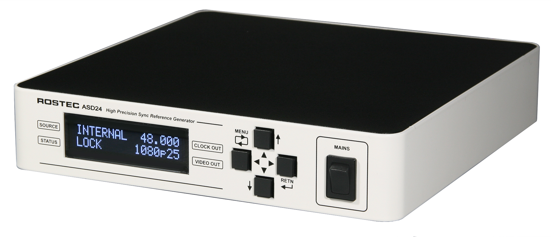
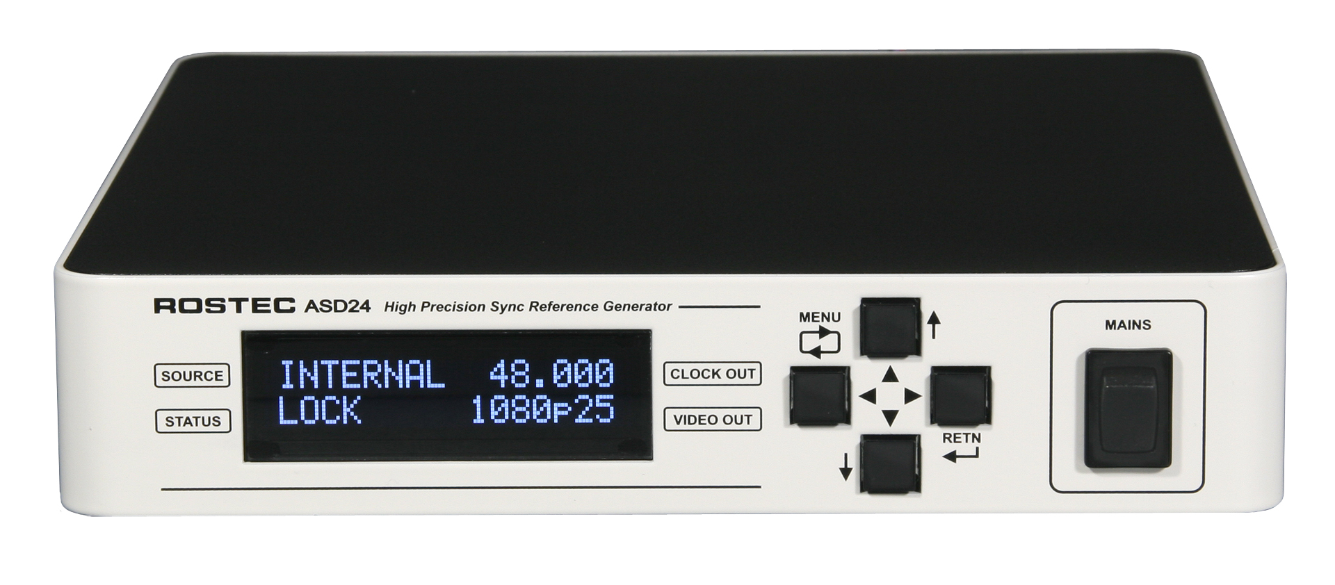
It has a straight forward and intuitive user interface with a clear “What You See Is What You Get” readout on a
bright OLED display. The display shows a real-time status of the chosen parameters, like video format, video
frame rate and Word Clock and AES/SPDIF frequencies. The display also shows the selected frequency
reference (internal or external) together with the lock/error status of the chosen reference.
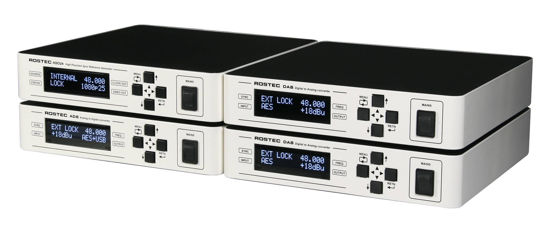
Click for larger pictures
Multiple units from the half-size box
series fit nicely in 19” rack systems
Features
* Easy and intuitive user interface
* Clear real time read-out of status on a bright OLED display
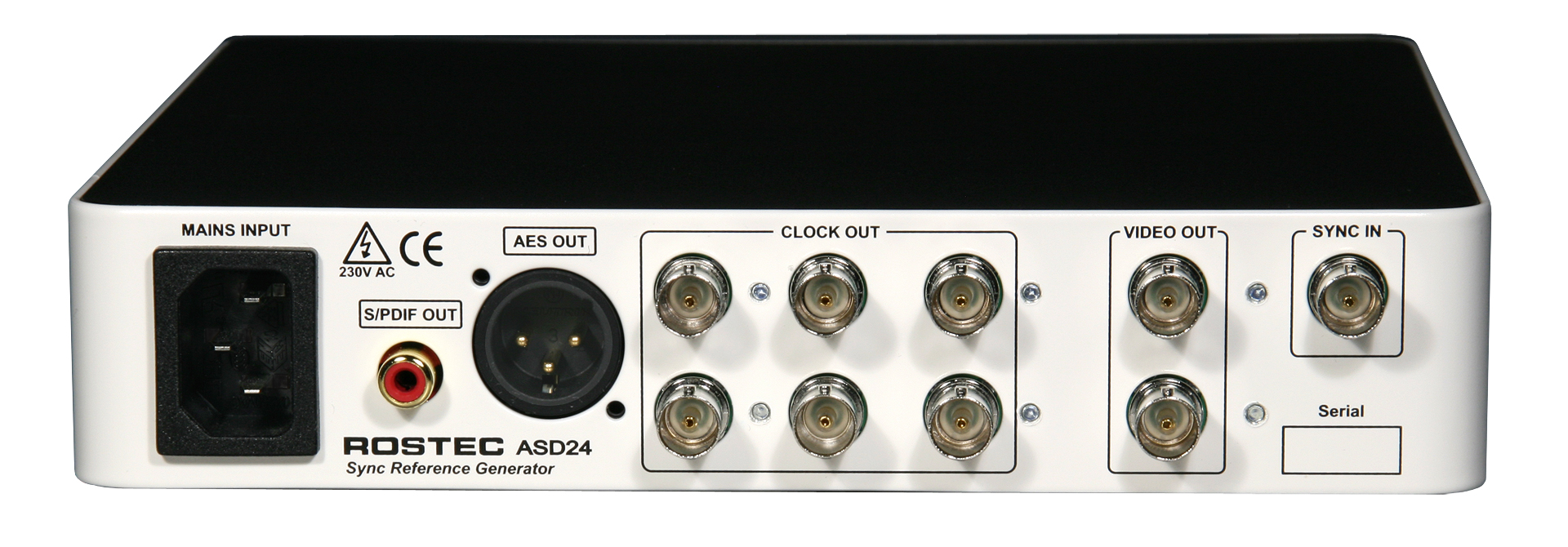
* 1 Sync input, BNC connector, 1.5 kohm, unterminated
• 2 Video outputs. BNC connectors, 75 ohm
• 6 clock outputs, BNC connectors, 75 ohm
• 1 AES 11 output. XLR male connector, transformer balanced 110 ohm
• 1 S/PDIF output. RCA connector, 75 ohm (downscaled AES, read the manual)
• 24 Video sync output formats
• 16 Word Clock output frequencies
* 6 AES/SPDIF output frequencies
* HD video tri-level sync
* SD video standard negative going sync
• Video test pattern, color bar for SD formats, hatch pattern (grid) for HD formats.
• Grade 1 internal oven reference crystal oscillator.
• Able to synchronize to standard audio Word Clocks, 10 MHz GPS (atomic clocks) 2.048 MHz E1 clock and 1.544 MHz T1
Telecom clock.
• Sync input accept from 0.2 Volts to 10 Volts.
• Sync Input with "sweet spot" detector, auto-slicing and signal clean-up for safe and jitter-free synchronization.
• Fly wheeling with soft glide when selecting between frequency references. Always continuous output! No drop-outs!
• Extremely low output jitter and wander, typically less than 80 psec RMS (0.08 nsec)
• Exceptional high immunity against jitter and digital noise from computer work stations.
• Linear low noise analog power supply.
• Internal magnetic and electrical screening.
• Inputs and outputs are ESD protected to 23 kV IEC 61000-4-2 and 15 A surge IEC 61000-4-5.
• Sturdy steel metal casing, electrically and magnetically screened.
• Stand-alone desktop, half size 19” standard.
• Small footprint. Dimensions: 210mm x 210mm x 42mm
• Weight 2,5 kg
General description
The heart of the ASD24 Reference Generator is a high grade crystal oscillator built into a temperature controlled oven together with all
the necessary voltage references and regulators for its operation. This scheme results in an excellent frequency stability over the
specified temperature range, far superior to a standard temperature compensated crystal oscillator. The frequency accuracy is better
than 0.1 ppm from 0 to +50 C. The factory adjustment is typically 0.05 ppm at 25 C.
The ASD24 always uses this oscillator as the central source for all Video, Word Clock and AES/SPDIF outputs, no matter whether the
generator runs on its own, or if it is locked to an external sync source.
The sync input is meant to be used with an ultra high accuracy house clock, if such is available. When the generator locks to the external
sync, it simply tunes the internal crystal oscillator to the exact frequency of the incoming reference. The incoming sync accuracy is then
directly transferred to all outputs, independent of which output formats are chosen.
For example, when you sync the generator to a GPS disciplined Atomic Clock with an accuracy of 10E-12 (1/1.000.000 ppm),
ALL OUTPUTS will have an accuracy of 1/1.000.000 ppm.
Further, the generator does not jump into lock, but glides softly until a perfect lock is achieved. If the external sync signal is lost or
discontinued, the generator softly glides back to the internal reference, and while it is gliding back and fort between sync sources, it
continues to supply uninterrupted outputs. No interruptions, no disturbances. Always valid sync!
Word clock, AES and SPDIF signals are generated by a separate crystal oscillator clock, which is permanently locked to the video
encoder by means of a high precision low jitter phase locked loop. When the video output format is changed, the Clock/AES/SPDIF
outputs always follow with the correct relationship between video frame rate and clock frequency. Video, Clock, AES and SPDIF are
bound together like cogs in a gearbox, always correct. never wanders off.
When an integer relationship exists between video frame rate and AES block frequency (European standard), the AES block start (Z-
preamble) is positioned at the video frame start. The leading edge of the Word Clock (and the X-preamble of AES) is always positioned
at the video frame start, whenever the mathematical relationship allows for it. This is all in full accordance with the AES
recommendations.
Note that the ASD24 does NOT use the problematic and inaccurate approximation techniques found in DDS (direct digital synthesis) or
fractional frequency dividers. Using this technique will invariable result in unacceptable levels of jitter. Instead, the architecture of the
ASD24 is based on SAW oscillators (surface acoustic wave), hardware synchronous counters and phase-lock loops in order to maintain
the correct mathematical relationship between Video, Word Clock and AES/SPDIF outputs and sync input clocks. This topology
maintains total and accurate control of the relationship between all signals, so no drift between video and audio is possible!
ALL combinations between Input Sync, Video Format, Clock and AES/SPDIF outputs are allowed and valid. The internal locking
mechanism keeps all signals in an iron grip, with a mathematical relationship that cannot be broken apart.
The resulting flexibility is astounding. There are a total of 4992 combinations, and they are all allowed, precise and mathematically
correct.
More info can be found in the quick guides and in the manual.
Electrical and mechanical specifications
Sync Reference input
* Clock input, 1.5 kohm unbalanced, unterminated, 1 x BNC connector
* Input level 0.5 V - 10 V PP, square or sine
* Input reference: INTERNAL and 13 external clock frequencies, listed below*
* Clock input capture range: +/- 80 ppm.
* Lock time approx: 0.4 - 0.6 sec.
Video Sync Output:
* Video Sync Output, 75 ohm, SMPTE/EBU level, 2 x BNC connectors, individually buffered
* SD bi-level, negative going sync.
* SD, Colorbar test pattern (selectable)
* HD tri-level sync
* HD, HATCH test pattern (selectable)
* 24 Video Sync output formats and frame rates, listed below*
Word Clock Output:
* Word clock output, 75 ohm, 6 x BNC connectors, individually buffered
* Output level 5 Volt PP no load, (TTL level). 2.5 Volt PP into 75 ohm
* 16 word clock output frequencies, listed below*
AES output:
* AES3 format, transformer balanced, 110 ohm, 1 x XLR Male connector
* Output level 10 Volt PP no load, 5 Volt PP into 110 ohm (full swing buffer)
* 6 AES3 output frequencies, following the word clock frequencies as listed below*
SPDIF output:
* SPDIF output format, 75 ohm, 1 x RCA female plug
* Output level 1 Volt PP no load, 0.5 Volt PP into 75 ohm
* 6 SPDIF output frequencies, following the word clock frequencies as listed below*
Clock system:
* Internal GRADE 1, oven crystal oscillator.
* Accuracy: Factory calibrated to 0.05 ppm @ 25 deg C
* Temperature stability: +/- 0.1 ppm from 0 degC to +50 deg C.
* Ageing: 1 ppm per year.
* Internal crystal oscillator jitter: 2.4 ps rms.
* Video sync output jitter and wander: 80 ps RMS
* Word clock output jitter and wander: 80 ps RMS
* AES/SPDIF output data jitter and wander: 80 ps RMS.
Power supply:
* Linear analog, passively cooled, high power, very low noise.
* Thermally and overload protected.
* Mains voltage: Nominal 230 VAC, range 180 - 264 VAC 50-60 Hz (115 VAC version available by request).
* Power consumption: 10 Watts.
General:
* Sturdy steel casing, magnetically and electrically screened. Size 210 mm x 210 mm x 42 mm.
* Analog (PLL circuits) and digital circuits are magnetically and electrically isolated by screening and separate ground systems.
* All signal inputs and outputs are ESD protected to 23 kV 15 A surge (IEC61000-4-2 and IEC61000-4-5).
ASD24 front panel quick guide............
ASD24 back panel quick guide...........
ASD24 Technical/User Manual...........
Sync references (SOURCE on the front display)
1. INTERNAL internal oven crystal oscillator
2. 44.1 kHz standard audio sampling frequency
3. 48 kHz standard audio sampling frequency
4. 88.2 kHz standard audio sampling frequency
5. 96 kHz standard audio sampling frequency
6. 176.4 kHz standard audio sampling frequency
7. 192 kHz standard audio sampling frequency
8. 352.8 kHz audio sampling frequency from future audio equipment
9. 384 kHz audio sampling frequency from future audio equipment
10. 705.6 kHz audio sampling frequency from future audio equipment
11. 768 kHz audio sampling frequency from future audio equipment
12. 1.544 MHz clock from T1 Telecom systems
13. 2.048 MHz clock from E1 Telecom systems
14. 10 MHz clock from GPS receivers, Rubidium oscillators, Cesium oscillators (AKA atomic clocks)
Video Sync Outputs (VIDEO OUT on the front display)
1. PAL B
PAL B 25i
interlaced
(25.00000000 Hz)
2. NTSC
NTSC 29.97i
interlaced
(29.97002997 Hz)
3. 525p 59.94
ITU-BT 1362
progressive
(59.94005994 Hz)
4. 625p 50
ITU-BT 1362
progressive
(50.00000000 Hz)
5. 720p 23.98
SMPTE 296M-8
progressive
(23.97602398 Hz)
6. 720p 24
SMPTE 296M-7
progressive
(24.00000000 Hz)
7. 720p 25
SMPTE 296M-6
progressive
(25.00000000 Hz)
8. 720p 29.97
SMPTE 296M-5
progressive
(29.97002997 Hz)
9. 720p 30
SMPTE 296M-4
progressive
(30.00000000 Hz)
10. 720p 50
SMPTE 296M-3
progressive
(50.00000000 Hz)
11. 720p 59.94
SMPTE 296M-2
progressive
(59.94005994 Hz)
12. 720p 60
SMPTE 296M-1
progressive
(60.00000000 Hz)
13. 1035i 29.97
SMPTE 240M
interlaced
(29.97002997 Hz) * sync of 1035p 59.94
14. 1035i 30
SMPTE 240M
interlaced
(30.00000000 Hz) * sync of 1035p 60
15. 1080i 25
SMPTE 274M-6
interlaced
(25.00000000 Hz) * sync of 1080p 50
16. 1080i 29.97
SMPTE 274M-5
interlaced
(29.97002997 Hz) * sync of 1080p 59.94
17. 1080i 30
SMPTE 274M-4
interlaced
(30.00000000 Hz) * sync of 1080p 60
18. 1080p 23.98
SMPTE 274M-11
progressive
(23.97602398 Hz)
19. 1080p 24
SMPTE 274M-10
progressive
(24.00000000 Hz)
20. 1080p 25
SMPTE 274M-9
progressive
(25.00000000 Hz)
21. 1080p 29.97
SMPTE 274M-8
progressive
(29.97002997 Hz)
22. 1080p 30
SMPTE 274M-7
progressive
(30.00000000 Hz)
23. 1080psf 24
ITU-R BT.709-5
interlaced
(24.00000000 Hz)
24. 1080psf 23.98
Non Standard
interlaced
(23.97602398 Hz)
* see the manual for details
Word Clock Outputs (CLOCK OUT on the front display)
1. 44.1 kHz standard audio sampling frequency
2. 48 kHz standard audio sampling frequency
3. 88.2 kHz standard audio sampling frequency
4. 96 kHz standard audio sampling frequency
5. 176.4 kHz standard audio sampling frequency
6. 192 kHz standard audio sampling frequency
7. 352.4 kHz audio sampling frequency for future audio equipment
8. 384 kHz audio sampling frequency for future audio equipment
9. 705.6 kHz audio sampling frequency for future audio equipment
10. 768 kHz audio sampling frequency for future audio equipment
11. 1.4112 MHz audio sampling frequency for 1-bit converters
12. 1.536 MHz audio sampling frequency for 1-bit converters
13. 2.8224 MHz mostly for test bench or lab work
14. 3.072 MHz mostly for test bench or lab work
15. 5.6448 MHz mostly for test bench or lab work
16. 6.144 MHz mostly for test bench or lab work
AES/SPDIF Outputs (follows CLOCK OUT on the front display)
1. 44.1 kHz standard audio sampling frequency
2. 48 kHz standard audio sampling frequency
3. 88.2 kHz standard audio sampling frequency
4. 96 kHz standard audio sampling frequency
5. 176.4 kHz standard audio sampling frequency
6. 192 kHz standard audio sampling frequency
Note: At word clock output frequencies above 192 kHz, the AES/SPDIF outputs stay at 176.4 kHz at 44.1 kHz
base frequencies, and stay at 192 kHz at 48 kHz base frequencies.
Synchronizing of digital audio.
Digital audio equipment must be synchronized in order to communicate correctly between devices. Without synchronization, errors will
invariable occur, resulting in a variety of audible symptoms ranging from unclear fuzziness to downright ugliness.
The most commonly used signals for synchronization are Word Clock, AES and Video. The ASD24 supplies all of these signals with high
precision and totally correct mathematically relationship between all formats.
When digital audio units in a signal chain are allowed to run freely on their internal clocks, the lack of synchronization results in a range of
errors with a varying degree of degradation of audio quality as the consequence. Different products have different ways of dealing with this
error condition; none of them are truly satisfactory.
The most common symptoms of lack of proper synchronization are digital noise, clicking or stuttering, when audio frames are dropped or
repeated. Another, more subtle symptom is when samples within the audio frame are dropped or repeated. These kinds of errors can be
camouflaged to some extend by clever algorithms using extrapolation, but the price is always a lack of openness and a sense of fuzziness
of the sound.
Another very common error situation is when the computer OS or the DAW tries to cope with the lack of proper synchronization by invoking
Sample Rate Conversion. This is a sneaky error condition. Sample Rate Conversion kinda saves the situation, but it is mostly uncertain
when, or if, the system has activated this. The result of SRC is increased distortion and generation of non-harmonic overtones, and the
penalty is a kind of reduction of audio quality, that is hard to put you finger on. But it invariably leaves the user with a frustrating feeling of
not being able to reach the sound quality that he or she is working so hard to reach.
Warning for Mac users: When you select several digital audio units to run as an “Aggregated Device” in the midi-setup, you should NOT
select “allowed for drift”. Doing so will invoke Sample Rate Conversion with all the drawbacks mentioned above.
The ASD24 Reference Generator is the perfect remedy for all the above described errors. When you hook your system up to the ASD24,
the various digital units in the signal chain will be able to communicate correctly. Your system will start performing at its best, and the sound
you are working to hard to get, will immediately be reachable.
It is recommended that parallel sync signal connections should be used, i.e. each digital audio unit should be connected directly to the sync
output of the ASD24 Reference Generator. Connecting in a serial link (daisy chaining) should be avoided, as this may create ringing at the
word clock edges, impedance mismatch or sync delay, depending on the configuration.
Synchronizing digital video and digital audio.
A well known synchronization problem in multimedia, video and film production is timing issues between picture and sound. We all know
how annoying it is when watching a movie with the audio and video out of sync. The root of this problem can actually be found in both
recording and in post production.
Often in video and film recording, the audio equipment and the cameras are left running on their respective internal clocks, which means
they are slowly drifting in time away from each other. The accumulated time difference can be up to several hundreds milliseconds during
an one hour session, and it can be a bit of a pain to correct this in post production, simply because the time difference is not constant but
is progressing during the session. Hooking up both video and audio equipment to the ASD24 Reference Generator in the recording phase
will eliminate this problem at its roots, efficiently locking cameras and audio equipment to the same time reference.
In post production the dilemma is the same. Video and audio will slowly drift apart, if they are not kept in sync. Using the ASD24 to
synchronize your Work Station, video equipment and audio equipment in the studio will prevent picture and sound from running away in
time from each other. At the same time, synchronization will also ensure the optimum performance of the audio equipment.
The ASD24 Reference Generator has all the necessary outputs to eliminate the sync problems in audio recording and multimedia, video
and film production. It supplies all the normally used video sync formats, Word Clock formats and AES/SPDIF formats necessary for
proper synchronization in both recording and post production.
The circuit topology used in the ASD24 ensures that all sync signal outputs and inputs are firmly locked to each other like cogs in a
gearbox. No drift is possible! You can leave a session running on your Work Station and come back after years (!) All sync signals will still
be within the same couple of nanoseconds as they were when you left.